Types of Positive Displacement Compressors

In the article "Different Types of Compressors and Their Applications", we became familiar with various types of compressors and learned that compressors are generally categorized into two groups based on "product volume": positive displacement and dynamic. Now, in this article, we intend to delve deeper into the different types of "positive displacement" compressors and examine the operating mechanism of each one more closely.
We learned that positive displacement compressors are broadly classified into five main categories:
- Rotary lobe
- Rotary vane
- Rotary screw
- Liquid ring
- Reciprocating
Now, let’s take a closer look at each of these five types of compressors.
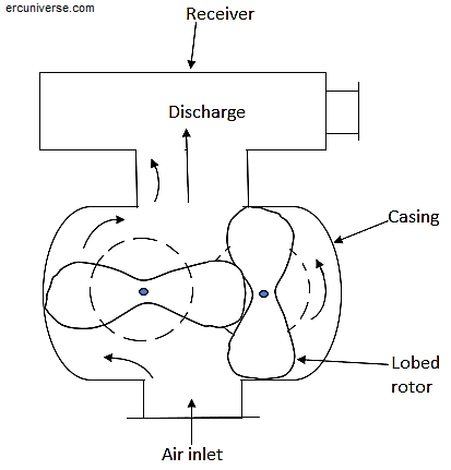
Rotary Lobe Compressor:

These compressors have identical and similar shafts that rotate simultaneously. The shafts are synchronized with each other through the use of external gearing, which is lubricated with oil. This synchronization prevents the shafts from colliding with each other and optimizes efficiency by minimizing the amount of play between the shafts.
Each shaft of the rotary lobe compressors consists of two lobes. As the shaft rotates, gas is trapped between the lobes of the shaft and the casing, and the rotating shaft compresses the gas from the inlet through the body to the outlet. The product of this process begins when the large edge of the lobe passes the edge of the outlet.
As the lobes extend, they compress the trapped gas towards the outlet, which compresses the gas against the back pressure from the system. Rotary lobe compressors are always noisy, and therefore, a silencer is typically included to reduce this noise.
Rotary Vane compressor:
A rotary vane compressor with sliding (slip) vanes consists of a series of vanes that freely slide along longitudinal grooves cut into the rotor. Centrifugal force causes the vanes to move outward against the wall of the casing. The space formed between the rotor and each vane and the casing creates a chamber. As the rotor turns, one vane passes through the inlet, forming a chamber between itself and the vane ahead of it. When that vane moves toward the end of the inlet, the volume of that chamber increases. As the chamber volume increases, it draws a portion of the vacuum inside the chamber and pulls the resulting vacuum from the gas inlet into itself. When the vane passes in front of the inlet, the chamber is sealed, and gas becomes trapped between the two vanes, the rotor, and the casing.

As the rotation continues toward the outlet, the volume of that chamber decreases. In this case, the vanes move against the casing and slide over the rotor. With the reduction in volume, the gas pressure increases, and the high-pressure gas is expelled from the outlet of the compressor. Rotary vane compressors are always quite noisy, which is a result of the movement of the vanes.
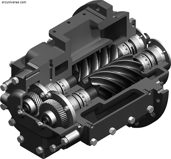
:Rotary Screw Compressor
Single-stage rotary screw compressors consist of a pair of rotors that engage with each other inside a cylinder that has two openings. The Male Rotor typically features 4 helical lobes spaced 90 degrees apart. The Female Rotor usually has 6 helical grooves spaced 60 degrees apart. The speed ratio of the rotors is inversely proportional to the ratio of grooves to lobes.
In a screw compressor with 4 lobes and 6 grooves, when the main rotor operates at 1800 revolutions per minute, the secondary rotor will operate at 1200 revolutions per minute. The main rotor is the driving rotor, while the secondary rotor is driven by the main rotor. In these compressors, to prevent metal-to-metal contact during operation, a film of oil is typically injected between the rotors. However, there are designs of these compressors that do not require lubrication, commonly referred to as "dry screw compressors."
In these compressors, the inlet opening is located at the end of the cylinder where the drive shaft is positioned. The outlet opening is placed directly opposite the inlet opening at the end of the cylinder.
In this compressor, gas is initially drawn into the cavity between the teeth of the main shaft and the groove of the auxiliary shaft. As the rotation continues, the teeth of the main shaft pass in front of the edges of the inlet openings, trapping the gas in a chamber formed between the cavities of the shaft and the cylinder wall. Further rotation causes the teeth of the main shaft to roll toward the groove of the auxiliary shaft, reducing the volume of gas trapped inside the chamber (Cell).
The reduction in volume within the chamber leads to an increase in pressure in this chamber. Meanwhile, oil is injected after the chamber is sealed off from the inlet opening. The injected oil seals the clearance between the teeth and grooves and also absorbs the heat generated from the compression of the gas.
Liquid Ring Compressor:
These compressors consist of a rotating shaft with several blades that rotate inside an oval-shaped casing. Part of this casing is filled with a liquid, usually water. As the shaft rotates, the blades form a series of buckets. During rotation, the buckets created by the blades carry the liquid along with the rotor. Since the fluid continues its path within the casing, it alternately fills and empties the space between the blades. When the fluid leaves this space, gas is drawn in from the inlet into the shaft chamber. As the shaft continues to rotate, the fluid returns to the shaft chamber, reducing the volume inside the chamber. When the volume decreases, the gas pressure increases. As the shaft chamber passes in front of the outlet, the compressed gas is discharged into a liquid-gas separator and then sent from there into the process system.

Reciprocating Compressor:
The main components of a reciprocating compressor include:
- Crankshaft
- Moving tongue that fits into the groove (for sliding motion)/ (Cross head)
- Piston rod seals
- Piston cylinder
- Suction and discharge valves
The figure below shows a three-stage reciprocating compressor.
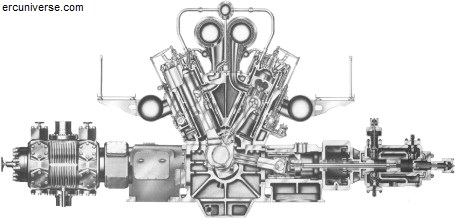
It is important to note that the cylinder and piston of the third stage are positioned above the cylinder and piston of the second stage. A starter motor (not shown in the diagram) rotates the crankshaft. The crankshaft converts the rotational motion of the drive into the reciprocating motion of the pistons. The compression cycle in the reciprocating compressor consists of two piston strokes, referred to as the "suction stroke" and the "compression stroke." The suction stroke begins when the piston moves away from the inlet port of the cylinder.
The gas present in the space between the piston and the inlet port rapidly expands until the pressure drops below the pressure on the opposite side of the suction valve. The pressure difference at the suction valve causes it to open, allowing gas to flow into the cylinder. The gas flows into the cylinder until it pushes the piston to the end of the stroke. The compressor stroke begins when the piston starts its return motion. When the pressure in the cylinder rises above the pressure on the opposite side at the suction valve, the suction valve closes, trapping the gas inside the cylinder.
As the piston continues its movement toward the end of the cylinder, the volume of the cylinder decreases, resulting in an increase in gas pressure. When the pressure inside the cylinder reaches its designed pressure, the discharge valve opens, and the contents of the cylinder are discharged into the suction section of the second stage. The second stage receives suction from the discharge of the first stage and compresses that gas to the final discharge pressure.
Conclusion:
In this article, we have generally introduced the types of positive displacement compressors, which specifically include five types: rotary lobe, rotary vane, rotary screw, liquid ring, and reciprocating.
Read our other articles to learn about other types of compressors, their applications, and other related topics. So, don’t miss the article "Dynamic Compressors and Their Operating Mechanisms"!
You Might Also Like
FAQs:
In rotary screw compressors, what is the relationship between the shaft speed ratio and the pitch-to-tooth ratio?
In rotary screw compressors, the shaft speed ratio is inversely proportional to the pitch-to-tooth ratio.
Which type of compressors is it more common to use silencers with?
In rotary lobe compressors, the use of silencers is common due to the high noise generated.
In reciprocating compressors, how many strokes does the compression cycle consist of?
The compression cycle in a reciprocating compressor consists of 2 piston strokes, known as the "suction stroke" and the "compression stroke." The suction stroke begins when the piston moves away from the cylinder's inlet port.